128X64 OLED LCD LED Display Module For Arduino 0.96\" I2C IIC Serial ( Blue/White)
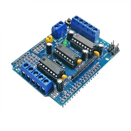
L293D MOTOR DRIVE SHIELD EXPANSION BOARD
【L293D】The motor shield is based on the L293, a full-bridge dual-driver designed to drive inductive loads such as relays, solenoids, DC motors, and stepper motors. It lets you drive two DC motors with your board, controlling the speed and direction of each independently. You can also measure the motor current draw of each motor, among other characteristics. The shield is compatible with 【Compact Design】The L293D is a monolithic 4-channel, high-voltage, high-current integrated circuit. Basically, this means you can use this chip with DC motors and power supplies up to 36 Volts. providing a maximum current of 600mA per channel, the L293D chip is also known as an H-bridge type. 【Motor Connections】 Brushed DC motor. You can drive two brushed DC motors by connecting the two wires of each into t
Delivery policy
(edit with the Customer Reassurance module)
(edit with the Customer Reassurance module)
سياسة الأرجاع
: الأرجاع في غضون 7 أيام بشروط أنقر لتفاصيل أكثر
: الأرجاع في غضون 7 أيام بشروط أنقر لتفاصيل أكثر
【L293D】The motor shield is based on the L293, a full-bridge dual-driver designed to drive inductive loads such as relays, solenoids, DC motors, and stepper motors. It lets you drive two DC motors with your board, controlling the speed and direction of each independently. You can also measure the motor current draw of each motor, among other characteristics. The shield is compatible with 【Compact Design】The L293D is a monolithic 4-channel, high-voltage, high-current integrated circuit. Basically, this means you can use this chip with DC motors and power supplies up to 36 Volts. providing a maximum current of 600mA per channel, the L293D chip is also known as an H-bridge type. 【Motor Connections】 Brushed DC motor. You can drive two brushed DC motors by connecting the two wires of each into the screw terminals (+) and (-) of each channel A and B. You can thus control its direction by adjusting the HIGH and LOW positions of DIR A and DIR B, you can control the speed by varying the duty cycle values of PWM A and PWM B. 【EASY OPERATION】You can measure the current flowing through the DC motor by reading the SNS0 and SNS1 pins. On each channel will be a voltage proportional to the measured current, which can be read like a normal analog input, via the analogRead() function on analog inputs A0 and A1. For your convenience, it is calibrated at 3.3 V when the channel delivers its maximum possible current, i.e. 2A.
MB19-5
إذا لم تكن راضيًا عن المنتج الذي اشتريته من websoog.com، أو إذا كان به عيب أو تعرض للتلف، يمكنك إعادته خلال 8 أيام من تاريخ التسليم، وسنقوم باستبداله. يُرجى ملاحظة أنه إذا تجاوزت الطلبية هذا المدة، فللأسف لن نقبل الإرجاع. المنتجات يتم استبدالها فقط، ولا يتم رد الأموال.
شروط استبدال المنتج
- إذا كان المنتج لا يتطابق مع الصورة المعروضة في الموقع.
- إذا كان المنتج يحتوي على عيب أو خلل.
- إذا كان المنتج تالفًا.
- إذا كان المنتج مقلدًا.
- إذا كان المنتج يفتقد بعض أجزائه.
- إذا لم تكن راضيًا عن المنتج بدون وجود أسباب من المذكورة أعلاه، ستتحمل تكاليف الإرجاع.
شروط تصوير الفيديو لضمان حقك في الإرجاع والتبديل
لضمان حقك وتجنب أي سوء تفاهم، يُرجى الالتزام بما يلي:
- قم بتصوير الطرد قبل فتحه مع توضيح الحالة الخارجية للتغليف.
- تأكد من ظهور الملصق الذي يحتوي على اسمك وعنوانك في الفيديو.
- استمر في التصوير أثناء فتح الطرد دون أي انقطاع، حتى يظهر المنتج بالكامل.
- بعد إخراج المنتج من الطرد، قم بتجربة المنتج أثناء تصوير فيديو متصل.
- إذا كان المنتج إلكترونيًا، أظهر عملية التشغيل والوظائف الأساسية.
- إذا لاحظت أي عيوب أو مشكلات أثناء الاستخدام، قم بتوضيحها بوضوح في الفيديو.
⚠️ ملاحظة: لن تُقبل الفيديوهات الناقصة أو التي تم تحريرها كدليل للإرجاع.
طريقة استبدال المنتج
1. الطريقة السريعة:
- عند استلام المنتج الجديد، ستدفع مبلغًا كضمان.
- ستقوم بتسليم المنتج القديم إلى مكتب التوصيل عند استلام المنتج الجديد.
- بعد استلامنا المنتج القديم، سنفحص حالته. إذا كان المنتج في حالة جيدة، سيتم تحرير مبلغ الضمان.
- إذا لم يكن المنتج في حالة جيدة، سيتم خصم جزء من مبلغ الضمان حسب حالته.
2. الطريقة الأطول:
- تقوم بإرسال المنتج إلينا للفحص. بعد التحقق من أنه في حالة جيدة، سنرسل لك منتجًا بديلاً. تستغرق هذه الطريقة وقتًا أطول.
منتجات غير قابلة للاستبدال
- المنتجات المفتوحة التي لا يمكن إرجاعها لأسباب صحية أو صحية.
- التسجيلات الصوتية/المرئية أو البرامج التي تم فتحها بعد التسليم.
- المنتجات المصنوعة حسب الطلب.
- المنتجات القابلة للتلف السريع.
- المحتوى الرقمي غير المقدم على وسائط مادية (مثل الأقراص).
- المنتجات كبيرة الحجم التي تتطلب تركيبًا (مثل الأثاث).
طلب الإرجاع
- قم بتسجيل الدخول إلى حسابك عبر الرابط التالي: تسجيل الدخول.
- املأ نموذج طلب الإرجاع مع إضافة الفيديو كدليل.
منتجات تم شراؤها من نفس العملاء:


