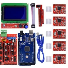
RAMPS 1.4 Kit + Mega 2560 + 5pcs A4988 + LCD 12864 Display For 3D Printer RepRap
: Vous pouvez voir les tarifs d'expédition et estimations de livraison cliquant ici
: Retour sous 7 jours avec conditions, cliquez pour plus de détails
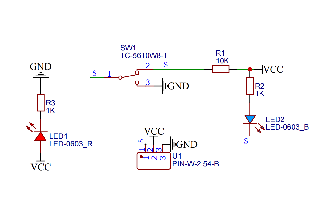
The collision switch module is essentially a micro snap-action switch, also known as a micro switch, which is an electronic switch activated by very small physical pressure. It can be directly connected to a single-chip microcomputer. It integrates the load resistor with the LED indicator. This makes it easier to test it. When physical pressure triggers the switch to close, the LED indicator on the board will light up. The principle of the collision switch is relatively simple, as shown in the following schematic diagram. When it is triggered to close by external force, the switch is closed and the module outputs a low level; when the external force is removed, the switch is opened and the module outputs a high level.
2. Schematic diagram
3. Module parameters
| Pin Name | describe |
|---|---|
| G | GND (negative pole of power input) |
| V | VCC (power input positive) |
| S | Digital signal pins |
Supply voltage: 3.3V / 5V
Connection method: PH2.0 terminal line
Installation method: double screw fixing
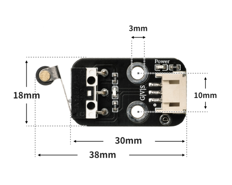
4. Circuit board size
Sample program (UNO development board):
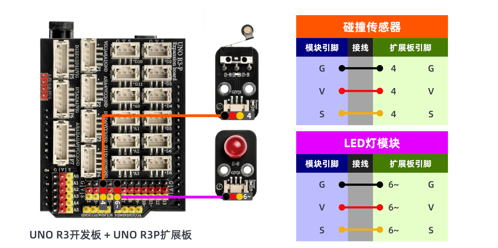
int limitswitchPin = 4; //Set the collision switch to pin D4
int led = 6; //Set the LED light to D6 pin
void setup() {

  Serial.begin(9600); //Set the serial port baud rate
  pinMode(limitswitchPin, INPUT); //Set the collision switch to input mode
  pinMode(led, OUTPUT); //Set led to output mode
}

void loop() {
  //Connect the collision switch to the D4 pin of the uno development board; connect the LED light module to the D6 pin

  if (digitalRead(limitswitchPin) == LOW) {//Press the collision switch
    Serial.println("Trigger the switch and light up the LED for 1 second");
    digitalWrite(led, HIGH);//Light up the LED
    delay(1000); //delay 1S

  } else {
    Serial.println("No switch is triggered, LED is off");
   digitalWrite(led, LOW); //Turn off LED

  }
  delay(500);

}
Sample program (ESP32 development board - based on Python language, can not use Arduino IDE to upload code):
import machine
import time


pin2 = machine.Pin(2, machine.Pin.IN)
pin4 = machine.Pin(4, machine.Pin.OUT)
while True:
    if pin2.value() == 0:
        pin4.value(1)
        time.sleep(1)
    else:
        pin4.value(0)
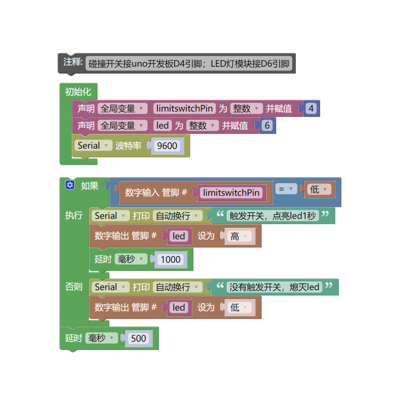
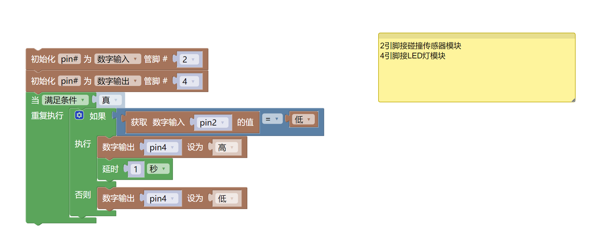
6. Mixly sample program (graphical language)
Sample program (UNO development board):
Sample program (ESP32 development board)
7. Test environment construction
Arduino environment construction
Prepare accessories:
- HELLO STEM UNO R3 development board*1
- HELLO STEM UNO R3 P expansion board*1
- USB type-c data cable*1
- LED light module (HS-F08P)*1
- Collision sensor module (HS-S31P)*1
- PH2.0 3P terminal to Dupont cable*2 or PH2.0 3P double-ended terminal cable*2
Circuit wiring diagram:
Micropython environment construction
Prepare accessories:
Circuit wiring diagram:
8. Video Tutorials
Video tutorial:
9. Test conclusion
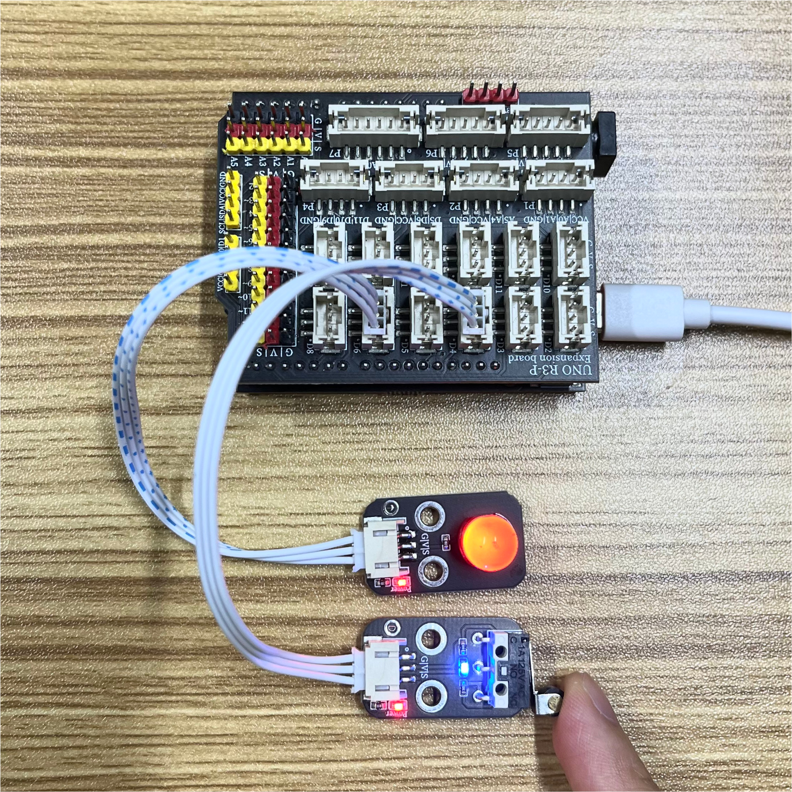
When the collision switch module is hit, the signal port of the collision switch module will output a low level. By judging the high and low level states of the signal port, the LED light is controlled to turn on and off. After the device is connected, burn the above program to the Arduino UNO development board, power on the mainboard, press the touch switch, the LED light turns on for 1 second, and the light turns off when it is released, achieving the purpose.


